Hybrid Wiring (UWP and EIM)
Equipment connected to both the thermostat and the EIM
RedLINK 3.0 ElitePRO thermostats support applications where equipment is installed in different locations, such as a heat pump and a boiler. Depending on the application, one of the following methods can be used:
Assignable Terminals: Certain application types allow you to choose whether a heating stage is wired to the thermostat or the EIM. Examples include radiant heat or the backup heat stage of a heat pump system. For more information, see Assigning Terminals.
Using an ERM4010: The ERM4010 can be used to control an outdoor unit or a radiant heat stage, including systems where radiant heat serves as the primary or backup heat source for a heat pump. See Installing Equipment Remote Module (if used) for wiring diagrams and setup instructions.
Mimicking: Mimicking allows selected terminals to be energized simultaneously at both the thermostat and the EIM. This feature is available only when pairing an ElitePRO thermostat with onboard relays to an EIM. For more information, see Mimicking Relays.
Assigning Terminals
The ElitePRO thermostat allows the installer the ability to assign certain terminals to provide application flexibility.
Radiant Heat combined with forced air
When controlling radiant heat, the thermostat will ask where the radiant heat stages are wired to. An ElitePRO thermostat with EIM4010 can:
-
Have the cooling equipment wired at the EIM4010 and the radiant heat assigned to be wired at the thermostat. If the reverse is needed, use an ERM4010* rather than the EIM4010.
-
Have the heat pump/air-handler wired at the EIM4010 and the radiant heat assigned to be wired at the thermostat. If the reverse is needed, use an ERM4010* rather than the EIM4010.
*The ERM4010 is never assigned terminals in the ISU (Installer Setup). If ERM4010 is configured for boiler by the J jumper, it will close the T terminals with a call for radiant heat in conjunction with the assigned terminal on the thermostat or EIM. If ERM4010 is configured for compressor by the J jumper, it will utilize the terminals as shown in the ERM wiring diagrams for conventional cooling, heat pump, or PTAC systems.
-
The ElitePRO Y, Y2, G, or O/B terminals are not assignable.
-
Y = Stage 1 compressor
-
Y2 = Stage 1 compressor or Stage 2 fan (Stage 2 fan assigned by thermostat when set for more than 1 fan speed)
-
G = Stage 1 fan
-
O/B = Reversing valve
-
-
Stage 1 heat will always be W/W1 for non-radiant heat systems that don't use a compressor for heat.
U terminals
The U terminals can control a humidifier, dehumidifier, ventilator, economizer, extra stage of heat or cooling, radiant heat stage, high speed fan for certain systems, or a custom dry contact output. ElitePRO thermostats have one set of U terminals on the thermostat. The EIM4010 has three sets of U terminals.
L terminal
The ElitePRO S1000, S1100, and the THX1200W5 or THX1200B6 models of S1200 thermostats allow the installer to assign the L terminal for use as an input or output. When paired with an EIM, the installer can use either the thermostat S terminal or EIM S1–S4.
Input
-
Fault signal from heat pump or economizer control.
-
Pipe sensor switch (Aquastat) from a 2-pipe fan coil unit.
-
Remote setback switch.
Output
-
Extra heat or cool stage.
-
Radiant heat stage.
-
Humidifier, dehumidifier, or ventilator control.
S terminals
S terminals can be set for a floor sensor, a wired indoor sensor, a wired outdoor sensor, a discharge air sensor, a return air sensor, a 10K or 20K pipe sensor for a 2-pipe fan coil unit, Pipe sensor switch (Aquastat) from a 2-pipe fan coil unit, a switch from a dry contact alert device (window sensor, water leak detector, etc.), or a remote setback switch. All ElitePRO thermostats have one set of S terminals on the thermostat. The EIM4010 has four sets of S terminals.
Mimicking Relays
How mimicking works
If any model of S1000, S1100, or S1200 ElitePRO thermostat that has onboard relays* is paired with the EIM4010, the thermostat can be set to use relay mimicking (ISU 3500) for the W, W2, Y, Y2, O/B, and G terminals that are not assigned.
Radiant heat stages are assigned to a specific terminal. Y2 is assigned to a medium or high speed fan when the thermostat is set for multiple fan speeds. W2/AUX** is assigned to a terminal when it is used as the backup heat for systems other than conventional forced-air heating.
Use cases for relay mimicking
Relay mimicking allows Pro installers to create unique installations such as:
-
Heating and cooling equipment located in different parts of the home.
-
Controlling two furnaces at the same time without a twinning kit. One furnace can be wired to the thermostat and the other to the EIM.
-
Staging a forced-air system with a ductless mini-split that uses an adapter board. A mini-split adapter board provided by the OEM would have R, C, W, Y, and G terminals for thermostat connection. The thermostat can be configured for a two-stage conventional system. Then:
-
R, C, W, Y, and G from the thermostat or EIM are wired to the equipment controlling Stage 1 heating/cooling.
-
R, C, W2, Y2, and G from the thermostat or EIM are wired to R, C, W, Y, and G on the equipment controlling Stage 2 heating/cooling.
-
The fan will be energized at both pieces of equipment on a cooling call (and on a heating call for system types in which the thermostat energizes the fan during heat). This provides better air circulation throughout the conditioned space.
*The THX1200W7S and THX1200B8S thermostats included in the YTHX1200W7 and YTHX1200B8 kits with EIMs have only one relay (U) in the thermostat and do not support Mimicking. To use Mimicking, one of the following ElitePRO thermostats and an EIM4010 must be ordered separately:
-
THX1200W5
-
THX1200B6
-
THX1100W3
-
THX1100B4
-
THX1000W1
-
THX1000B2
**When Mimicking is enabled on a thermostat used with an EIM4010, the W2/AUX and E terminals are energized simultaneously.
Hybrid Wiring Diagrams
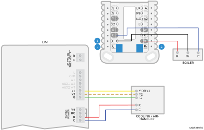
Thermostat wired to Boiler; Cooling wired to EIM4010

|
For ISU 2075, set the radiant heat to Thermostat U |

|
U and R slider switches up when thermostat C comes from boiler. If thermostat 24 volts is from a separate transformer, set the U slider down, wire transformer to R and C and wire boiler to U and U. |
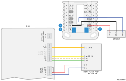
Thermostat wired to Boiler; Heat pump wired to EIM
|
|
For ISU 2170, set the backup heat to Thermostat U |
|
|
U and R slider switches up when thermostat C comes from boiler. If thermostat 24 volts is from a separate transformer, set the U slider down, wire transformer to R and C and wire boiler to U and U. |
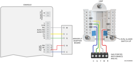
Staging a Gas Furnace & AC system with a Ductless Minisplit
|
|
The “mimic” feature is enabled with ISU 3500 allows the W1, W2, Y1, Y2, O/B and G terminals to be energized at both the thermostat and EIM. This feature only works when using a Redlink ElitePRO that has onboard relays (not the ones kitted with EIM) |
|
|
ElitePRO thermostat can only control ductless minisplits that have an adapter board which allows control from a regular thermostat. |

|
In this example, the Minisplit is used for stage 1 heating/cooling and the forced air furnace and AC is acting as stage 2 heating/cooling. |

|
To better distribute air throughout the home with a stage 1 heat or cool call, set the system type to a 2-stage electric forced air furnace and 2 stage cooling, and set ISU 2110 to “Thermostat controls fan”. That way the furnace fan runs with the minisplit on a heat or cool call. Note: The furnace fan will run with a call for stage 1 cooling regardless of ISU 2110. |

|
Change the heat cycle rates to 3 (ISU 3150). |

|
There are different options for staging control. Normally the thermostat uses an algorithm to determine when to go to stage 2. ISU settings 3030 and 3050 allow you to set a stage 2 differential for heat and cooling if you prefer. |