Wiring Diagrams
Wiring an ElitePRO™ Series Thermostat without EIM
-
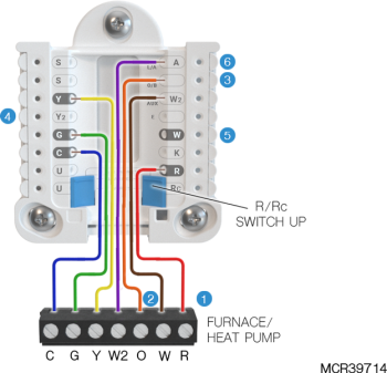
Use 18- to 22- gauge thermostat wire. Shielded cable is not required.
-
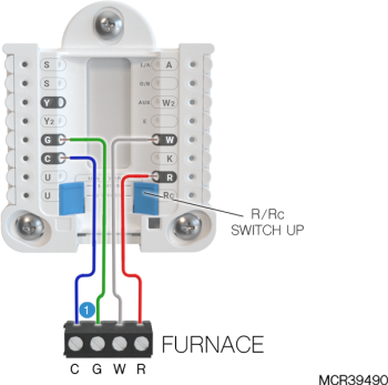
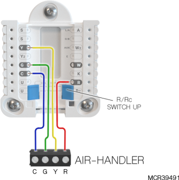
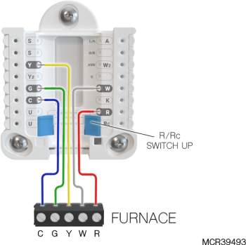
Set the R Slider Tab on the UWP to the up position (1 wire) for 1 transformer systems or the down position (2 wires) for 2 transformer systems.
-
Set the U Slider Tab to the position shown for IAQ wiring diagrams on Using U Terminals.
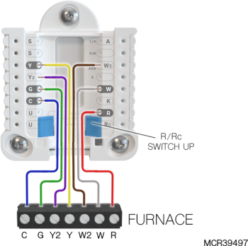
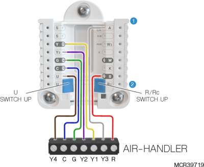
Heat only: Gas. Oil, or Electric furnace
Cool only
1H/1C gas or Electric furnace
2H/1C gas furnace
2-transformer system; 1H/1C oil furnace
![]()
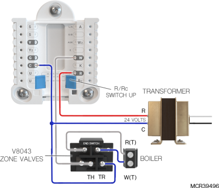
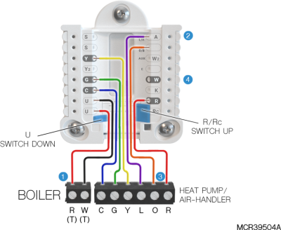
2-transformer system; hot water heat with air-conditioning (or hot water coil)
![]()
Hot water heat with power open zone valve
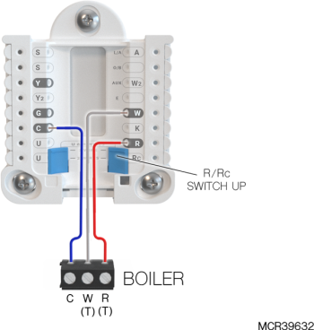
Hot water boiler, heat only
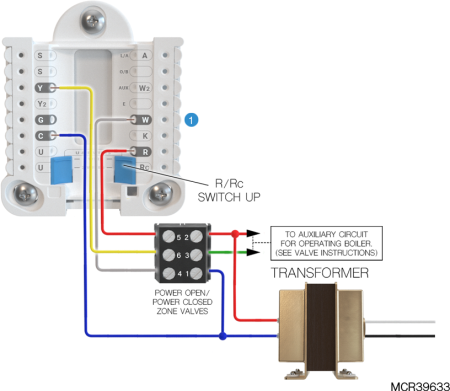
Series 20 valve (power open and power closed)

|
Thermostat must be configured for radiant heat with 0 (zero) cool stages. |
2H/2C Gas Furnace
Wiring a third and fourth Cool stage without EIM
|
|
S900 models of ElitePRO™ Series Thermostats cannot use L/A for a cool stage. Verify ISU settings 2080 & 2090 match wiring. The L/A and U wires may be reversed. |

|
If heating (not shown) uses a different transformer than cooling, cooling transformer goes to Rc and the R/Rc slider should be down. |
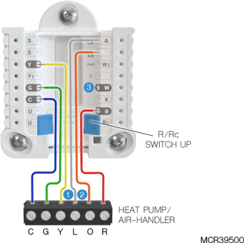
1H/1C Heat Pump without Aux Heat
|
|
L only connected if heat pump has a fault terminal. |
|
|
Some heat pumps use B rather than O for reversing valve. |

|
IMPORTANT: DO NOT connect any wire to W for heat pump applications! This can cause heat to run continuously. |
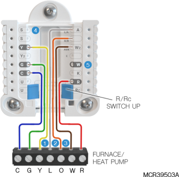
Dual fuel 2H/1C Heat pump
|
|
L only connected if heat pump has a fault terminal. |
|
|
Some heat pumps use B rather than O for reversing valve. |
|
|
The furnace and Heat Pump have separate boards. We show them together to simplify the diagram. W is from the Furnace board. |

|
Balance point lockout can be done through router/internet connection and App, wired outdoor sensor or wireless outdoor sensor. |

|
DO NOT connect any wire to W for heat pump applications! This can cause heat to run continuously. |
Dual Fuel, 3H/2C Heat Pump
|
|
Common Required. |
|
|
L only connected if heat pump has a fault terminal. |
|
|
Some heat pumps use B rather than O for reversing valve. |
|
|
The furnace and Heat Pump have separate boards. We show them together to simplify the diagram. W is from the Furnace board. |
|
|
Optional: C7089U1006 Wires to the two S terminals. |

|
DO NOT connect any wire to W for heat pump applications! This can cause heat to run continuously. |
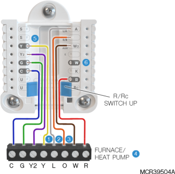
Dual fuel with 2-stage Furnace
|
|
Terminals used for furnace chose in ISU 2170 and 2171. Verify these setting match the wiring. |
|
|
The furnace and Heat Pump have separate boards. We show them together to simplify the diagram. W and W2 are from the Furnace board. |
|
|
Some heat pumps use B rather than O for reversing valve. |
|
|
Connect Y2 (not shown) for 2 stage compressor if used. |
|
|
DO NOT connect any wire to W for heat pump applications! This can cause heat to run continuously. |
|
|
L/A terminal can be used for furnace stage 2 on S1000, S1100 and S1200 models. Alternately, the upper U terminal could be used for stage 2 furnace on any ElitePRO model. |
Heat Pump with Boiler
|
|
Verify ISU 2170 is set to use U for backup heat. |
|
|
L only connected if heat pump has a fault terminal. |
|
|
Some heat pumps use B rather than O for reversing valve. |
|
|
DO NOT connect any wire to W for heat pump applications! This can cause heat to run continuously. |
Fan Coil Unit Wiring Diagrams without EIM
Typical wiring of 4-pipe fan coil
|
|
The high speed fan could alternately be wired to L/A on S1000, S1100 or S1200 models. Verify the wiring matches the ISU 2107. If wired to U, the U slider switch should be set to the up position as shown. |
|
|
The R/Rc slider switch should be set to the up position as shown. |
|
|
S terminals can be used for a wired indoor sensor or outdoor sensor. See the Remote setback wiring options if a sensor/switch was wired to S terminals on previous thermostat. |
Typical wiring of 2-pipe fan coil with reheat using wired 10K/20K Heat/cool changeover pipe sensor
|
|
The high speed fan could alternately be wired to L/A on S1000, S1100 or S1200 models. Verify the wiring matches the ISU 2107. If wired to U, the U slider switch should be set to the up position as shown. |
|
|
The R/Rc slider switch should be set to the up position as shown. |
|
|
S terminals can be used for a wired 10K or 20K pipe sensor for heat/cool changeover. |
Typical wiring of 2-pipe fan coil without reheat
using wired 10K/20K Heat/Cool changeover pipe sensor

|
|
The high speed fan could alternately be wired to L/A on S1000, S1100 or S1200 models. Verify the wiring matches the ISU 2107. If wired to U, the U slider switch should be set to the up position as shown. |
|
|
The R/Rc slider switch should be set to the up position as shown. |
|
|
S terminals can be used for a wired 10K or 20K pipe sensor for heat/cool changeover. |
Typical wiring of 2-pipe fan coil with reheat using dry contact switch for Heat/Cool changeover
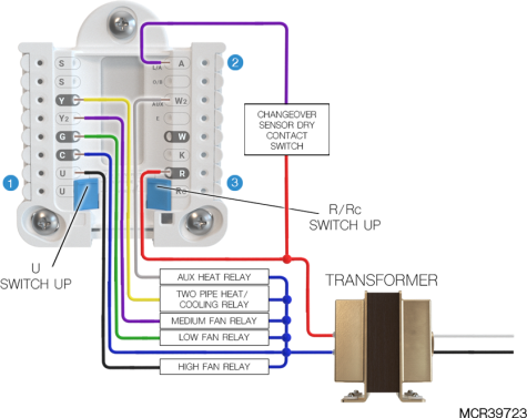
|
|
Verify the wiring matches the ISU 2107. If wired to U, the U slider switch should be set to the up position as shown. |
|
|
Wire the dry contact changeover switch to R at the fan coil unit and L as shown. ElitePRO™ Series Thermostats can be configured for the changeover switch to be normally open in cool or heat mode. See ISU settings 2054 & 2055. |
|
|
The R/Rc slider switch should be set to the up position as shown. |
Typical wiring of 2-pipe fan coil without reheat
using dry contact switch for Heat/Cool changeover
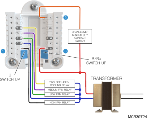
|
|
Verify the wiring matches the ISU 2107. If wired to U, the U slider switch should be set to the up position as shown. |
|
|
Wire the dry contact changeover switch to R at the fan coil unit and L as shown. ElitePRO™ Series Thermostats can be configured for the changeover switch to be normally open in cool or heat mode. See ISU settings 2054 & 2055. |
|
|
The R/Rc slider switch should be set to the up position as shown. |
PTAC with multiple fan speeds
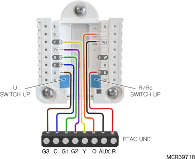
|
|
Some PTAC units use B rather than O for reversing Valve. |
|
|
Do not wire to W on UWP for PTAC systems. If the system has auxiliary heat this must wire to AUX. If the system does not have auxiliary heat the dotted line from this diagram is not used. |
|
|
S terminals can be used for a wired sensor. L/A terminal can be used for remote setback. Other diagrams show this optional equipment. |
Whole house humidifier, dehumidifier, or ventilator wiring
Using U Terminals
Wired to humidifier, dehumidifier, or ventilator
with built-in transformer
![]()
Wired to fresh air damper powered by furnace transformer
![]()
Wired to humidifier, ventilator or damper powered
by external transformer
![]()
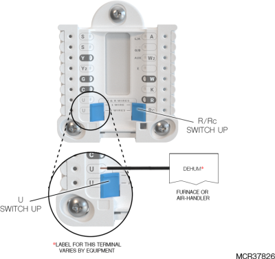
Wired to low speed fan terminal on HVAC for dehumidification
Using the L terminal to control IAQ (S1000, S1100, & S1200 only)
L/A Wired to humidifier, dehumidifier, or ventilator
with built-in transformer
![]()
|
|
Verify ISU 10020 is set to use L for ventilation rather than U. |
|
|
An R8222B or equivalent low-voltage-rated relay could be used. |
|
|
Furnace/Air-handler wiring varies by system. See system wiring diagrams for system wiring. |
L/A wired to humidifier or vent damper powered by furnace transformer transformer
![]()
|
|
Verify ISU 8030 (humidifier) or 10020 (ventilator) is set to use L/A rather than U. This wiring is only for a vent damper or a humidifier which does not have a built-in transformer. |
|
|
Furnace/Air-handler wiring varies by system. See system wiring diagrams for system wiring. |
|
|
Verify system transformer is sized to handle additional load of humidifier or vent damper. |