Installing Equipment Interface Module (if used)
-
Mount the EIM near the HVAC equipment or on the equipment itself. Use screws and anchors as appropriate for the mounting surface.
-
To wire the EIM, strip 1/4” insulation, then insert wires (For wiring diagrams, see EIM Wiring Diagrams.)

Strip 1/4” insulation, then insert wires as shown.
EIM Wiring Diagrams
Typical wiring of a conventional system with up to 3 stage Heat and 2 stage Cool with one transformer

|
|
Remove jumper(s) if using separate transformers. |
|
|
NOTE:See following pages for additional thermostat wiring guidelines for other system types, sensor wiring, IAQ Control, and other dry contact wiring options. |


Wiring a third cool stage with EIM

|
|
Any set of U terminals (U1, U2, U3) can be assigned to control stage 3. Jumper the other U from that set to Rc as shown. |
Typical wiring of a heat pump system with up to four-stage Heat and two-stage Cool with one transformer

|
|
Remove jumper(s) if using separate transformers. |
|
|
The changeover valve will be labeled O if energized in cool or B if energized in heat. |
|
|
The Auxiliary heat stage(s) are labeled differently on different heat pump air handlers. Most heat pumps applications only have one stage of auxiliary heat. |
|
|
NOTE:See following pages for additional thermostat wiring guidelines for other system types, sensor wiring, IAQ Control, and other dry contact wiring options. |


Typical wiring of a Dual Fuel heat pump system with 1 or 2-stage furnace and 1 or 2-stage heat pump
|
|
Remove jumper(s) if using separate transformers. |
|
|
The changeover valve will be labeled O if energized in cool or B if energized in heat. |
|
|
The Heat Pump and Furnace have separate boards, they are shown together here to simplify this diagram. |
|
|
NOTE:See following pages for additional thermostat wiring guidelines for other system types, sensor wiring, IAQ Control, and other dry contact wiring options. |
Typical wiring of a heat pump system with boiler backup

|
|
Remove jumper since the boiler has a separate transformer than the heat pump. |
|
|
The changeover valve will be labeled O if energized in cool or B if energized in heat. |
|
|
If using a hot water relay panel, the wires shown going to the boiler would instead wire to R and W on one of the zones of the panel. |
|
|
NOTE:See following pages for additional thermostat wiring guidelines for other system types, sensor wiring, IAQ Control, and other dry contact wiring options. |
Typical wiring of a heat pump system with a zone valve for Backup Heat

|
|
Remove jumper since the valve is powered by a separate transformer than the heat pump. |
|
|
The changeover valve will be labeled O if energized in cool or B if energized in heat. |
|
|
The wires that power the valve are shown on the left side of the valve. The end-switch wires from the valves go to the boiler. |
|
|
NOTE:See following pages for additional thermostat wiring guidelines for other system types, sensor wiring, IAQ Control, and other dry contact wiring options. |
Typical wiring of a spring-closed, power-open zone valve with end-switch

|
|
If also controlling cooling with a separate transformer, remove RH at EIM. Valve transformer C would not wire to EIM. Cooling transformer wire to R and C with R to RC jumper installed. |
|
|
The wires that power the valve are shown on the left side of the valve. The end-switch wires from the valves go to the boiler. |
|
|
If using an AC112-01 or equivalent slab sensor, wire that to any of the 4 sets of S terminals on EIM and make sure the ISU Settings match the wiring. |
Typical wiring of a series 20, power-open/power-closed zone valve

|
|
If also controlling cooling with a separate transformer, remove RH Jumper wire the valve transformer to RH at EIM. Valve transformer C would not wire to EIM. Cooling transformer wire to R and C with R to RC jumper installed. |
|
|
If using an AC112-01 or equivalent slab sensor, wire that to any of the 4 sets of S terminals on EIM and make sure the ISU Settings match the wiring. |
|
|
NOTE:See following pages for additional thermostat wiring guidelines for other system types, sensor wiring, IAQ Control, and other dry contact wiring options. |
Fan Coil Unit Wiring Diagrams with EIM
Typical wiring of 4-pipe fan coil

|
|
Any set of U contacts can be set to control high speed fan. One of those U contacts must be jumped to the fan coil transformer R as shown. |
|
|
S terminals can be used for a wired indoor sensor or outdoor sensor. |
|
|
If a remote setback switch is used, that switch wires to any set of S terminals at the EIM. Configure ISU settings 2240, 6010, 6020, 6030, & 6040 on the T10+ for remote setback. |
Typical wiring of 2-pipe fan coil with reheat using wired 10K/20K Heat/Cool changeover pipe sensor

|
|
Any set of U contacts can be set to control high speed fan. One of those U contacts must be jumped to the fan coil transformer R as shown. |
|
|
S terminals can be used for a 10K or 20K pipe sensor for Heat/Cool changeover. |
|
|
If a remote setback switch is used, that switch wires to any set of S terminals at the EIM. Configure ISU settings 2240, 6010, 6020, 6030, & 6040 on the T10+ for remote setback. |
Typical wiring of 2-pipe fan coil without reheat using wired 10K/20K Heat/Cool changeover pipe sensor

|
|
Any set of U contacts can be set to control high speed fan. One of those U contacts must be jumped to the fan coil transformer R as shown. |
|
|
S terminals can be used for a 10K or 20K pipe sensor for Heat/Cool changeover. |
|
|
If a remote setback switch is used, that switch wires to any set of S terminals at the EIM. Configure ISU settings 2240, 6010, 6020, 6030, & 6040 on the T10+ for remote setback. |
Typical wiring of 2 pipe fan coil with reheat using dry contact switch for heat/cool changeover

|
|
Any set of U contacts can be set to control high speed fan. One of those U contacts must be jumped to the fan coil transformer R as shown. |
|
|
Wire the dry contact changeover switch to R at the fan coil unit and L at EIM as shown. T10+ can be configured for the changeover switch to be normally open in Cool or Heat mode. |
Typical wiring of 2 pipe fan coil without reheat using dry contact switch for Heat/Cool changeover

|
|
Any set of U contacts can be set to control high speed fan. One of those U contacts must be jumped to the fan coil transformer R as shown. |
|
|
Wire the dry contact changeover switch to R at the fan coil unit and L at EIM as shown. T10+ can be configured for the changeover switch to be normally open in Cool or Heat mode |
Typical wiring EIM to a hot water relay panel

|
|
RH jumper removed. EIM powered by separate transformer. |
|
|
If using an AC112-01 or equivalent slab sensor for the zone controlled by the thermostat, wire that to any of hte 4 sets of S terminals on EIM and make sure the ISU settings math the wiring. |
Typical wiring EIM to a Resideo TrueZONE forced air zone panel for conventional heat

|
|
R to Rc jumper removed if EIM is powered by a separate transformer. |
|
|
Zone 4 is shown in this drawing. The EIM can wire to any zone on the TrueZONE panel. |
|
|
Dotted lines for Multistage only. |
|
|
Wire the dampers, transformer and HVAC to zone panel as shown in zone panel installation guide. |
|
|
It is not recommended to use a discharge sensor with the EIM on a zoned system. A discharge sensor can be wired to the zone panel for High and Low limit temperature protection. |


Typical wiring EIM to a Resideo TrueZONE forced air zone panel for heat pump with electric Aux Heat application

|
|
R to Rc jumper removed if EIM is powered by a separate transformer. |
|
|
Zone 4 is shown in this drawing. The EIM can wire to any zone on the TrueZONE panel. |
|
|
Y2 is for 2 stage compressor only. |
|
|
Add a jumper from W1/E to W3 at zone panel if Y2 is used. Add a jumper at zone panel from W1/E to W2 if Y2 is not used. |
|
|
Wire the dampers, transformer and HVAC to zone panel as shown in zone panel installation guide. |
|
|
It is not recommended to use a discharge sensor with the EIM on a zoned system. A discharge sensor can be wired to the zone panel for High and Low limit temperature protection. |

Typical wiring EIM to a Resideo TrueZONE forced air zone panel for dual fuel heat pump application

|
|
R to Rc jumper removed if EIM is powered by a separate transformer. |
|
|
Zone 4 is shown in this drawing. The EIM can wire to any zone on the TrueZONE panel. |
|
|
W2 is for 2 stage furnace only. |
|
|
Y2 is for 2 stage compressor only. |
|
|
Wire the dampers, transformer and HVAC to zone panel as shown in zone panel installation guide. |
|
|
It is not recommended to use a discharge sensor with the EIM on a zoned system. A discharge sensor can be wired to the zone panel for High and Low limit temperature protection. |
Wiring Dry Contact Alerts with EIM
Dry contact alerts

U terminals can be used for humidification, dehumidification or ventilation

|
|
Any combination of relays (U1, U2, U3) can be used. They are set in the thermostat Installer Setup. |
|
|
Wire the U relay to the low speed fan for dehumidification control at the equipment. The EIM relay can be set to normally open or normally closed in the thermostat Installer Setup. |
|
|
An optional 50027910-001 Air-Flow switch (AFS) is recommended to ensure aire flow when the humidifier is running. If the AFS is used, set dip switch 1 to Off (Left). The T10+ can be configured to only run the humidifier with a call for heat or fan, so the AFS would only be needed to ensure no water flow through the humidifier pad if there is a fan failure. The T10+ can alternately be configured for a fan failure alert (ISU 6000, 6150 and 6160). |
Linking the T10+ to an Optional EIM
-
When the T10+ is powered, follow the onscreen prompts until you see Do you have an Equipment Interface Module (EIM)?.
Select Yes, I have an EIM.

-
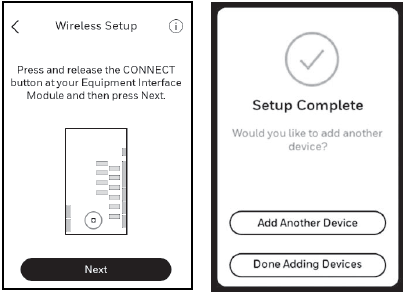
Press and release the CONNECT button at the EIM when the thermostat prompts you. Make sure the “Connected” lights is flashing green. The EIM will continue to flash the connected light for 15 minutes and reset this timer every time a new RedLINK 3.0 device is added.
-
Green Flashing: In Listening Mode. System is ready to add RedLINK 3.0 devices.
-
Green Steady: RedLINK 3.0 devices are communicating.
-
Red: RedLINK 3.0 device(s) are not communicating. Check EIM and RedLINK devices.

EIM Connect Button
NOTE: If the CONNECTED light does NOT flash green, another system may be in Listening Mode. Please exit Listening Mode on the other system and try again.
- Return to the thermostat and press Next (shown in the left image below).
-
Adding RedLINK 3.0 Accessories to the T10 or T10+ Thermostat.
NOTE: The EIM and wireless outdoor sensor can only be connected to a T10+. The T10 installation will skip the EIM section and go directly to the wireless indoor sensor during initial setup.
-
Select Add Another Device and follow the prompts on screen.
-
Install batteries in RedLINK 3.0 accessories.
-
Wireless Outdoor Sensor RedLINK 3.0 C7089R3013 (T10+ only).
-
Wireless Indoor Sensor; C7189R3002 or C7189R2002 (C7189R2002 no longer sold and not compatible with T10+ models).
-
Connect each RedLINK 3.0 accessory.
NOTE: Make sure RedLINK 3.0 accessories are at least 2 feet away from the thermostat (or EIM, if used) during the linking process.
-
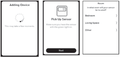
While the “Connect Device” screen is displayed (Listening Mode), press and quickly release the CONNECT button on each new RedLINK 3.0 accessory.
-
After a short delay (up to 20 seconds), check the thermostat to confirm the connection of each RedLINK 3.0 accessory.
NOTE: If adding a wireless indoor sensor or wireless outdoor sensor (outdoor on T10+ only) after the initial setup has been completed, go to Menu > Installer Options > Devices and Sensors, and select Add.
-
Follow the instructions on thermostat screen. After each RedLINK 3.0 accessory is added and any follow up questions are set, the thermostat will ask if you want to add another device or are done adding devices.
NOTE: Examples of follow up questions and instructions for the wireless indoor sensor shown below.
-
Once all RedLINK 3.0 accessories have been added and you have completed the on-screen follow-up questions and instructions, the display will say “Setup Complete". Select Done Adding Devices.
-
Follow the onscreen display instructions to complete system setup for heating and cooling type, humidifier, dehumidifier, ventilator settings, etc.

To Replace the Equipment Interface Module (EIM)
When you replace an EIM, you must reset the RedLINK 3.0 accessories before connecting them to the new thermostat. Follow the instructions below:
At the Indoor Sensor or other RedLINK 3.0 accessory:
Press and hold the CONNECT button on the accessory until the status light glows amber (hold for about 10 seconds). To reconnect the thermostat, go to Step 4.
At the thermostat:
Go to Installer Options, choose Reset, then Factory reset. This will clear the EIM and any other RedLINK 3.0 devices from T10+ as well as the system settings. After doing Factory Reset, follow thermostat prompts to link new EIM and configure system settings.
To replace a T10+ connected to an EIM
Press and hold the connect button on the EIM until the connect light turns amber approximately 10 seconds. This should clear the EIM from the thermostat and any RedLINK 3.0 accessories. Then it is ready to be connected to a new T10+ thermostat using the original setup process.
NOTE: The new T10+ will also guide you through the setup steps during initial setup when you choose that you have an EIM.
EIM Connect Button