Mounting and Wiring
Video: Mount and Wire the X2P thermostat
|
Tools you will need:
|
Tools you may need:
|
Removing the Old Thermostat
-
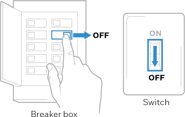
Turn power OFF. To protect yourself and your equipment, turn off the power at the breaker box or switch that controls your heating/cooling system. Some systems may have separate heating and cooling breakers.
-
Check that your system is off.
-
Change the temperature on your old thermostat to be above room temperature in heat mode or below it in cool mode.
-
If you don’t hear the system turn on within 5 minutes, the power is off.

If you have a digital thermostat that has a blank display, skip this step.
-
-
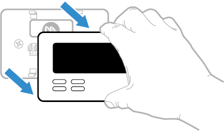
Remove the old thermostat’s faceplate. On most thermostats, you can take off the faceplate by grasping and gently pulling. Some thermostats may have screws, buttons, or clasps.
Do not remove any wires from your thermostat at this time!
-
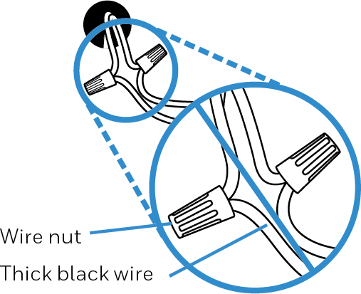
Make sure there are no 120/240V wires.
Do you have thick black wires with wire nuts?
Is your thermostat 120V or higher?
If you answered yes to either of these questions, you have a line voltage system and the thermostat will not work.
-
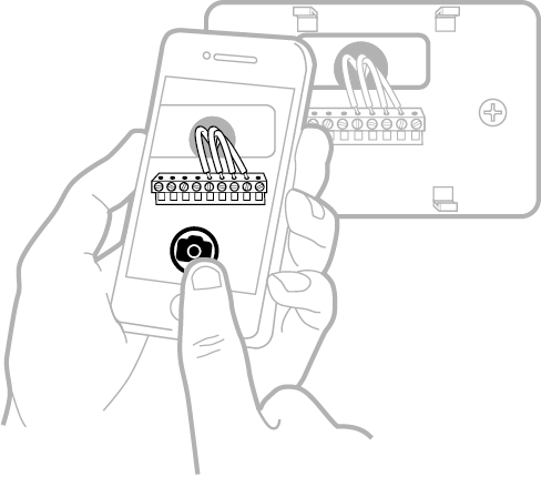
Take a picture of how your wiring looks right now. Be sure to include the letters next to the terminals where the wires are inserted. This will be a helpful reference when wiring your thermostat.
If the color of your wires has faded or if 2 terminals have the same wire color, use the wire labels provided in the package to label each wire.
-
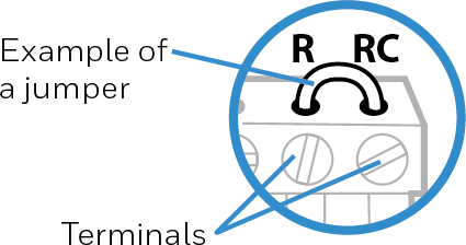
Make note of any jumpers. A jumper connects one terminal to another terminal. It may look like a small staple or even a colored wire.
-
Make note of whether you have wires in the following terminals. Do not include jumpers as a part of your count. This thermostat does not need jumpers.
-
Write down the color of the wires. Check mark the wires that are connected to terminals. Next to the check mark, write down the color of the wire. Do not include jumpers as a part of your count. Check all that apply (Not all will apply):
-
Disconnect the wires and remove the old wall plate. Use a screwdriver to release wires from terminals. Then, use a wire label to identify each wire as it’s disconnected. The letter on the wire label should match the letter on the terminal.
To prevent wires from falling back into the wall, wrap the wires around a pencil.
Mounting your X2P Thermostat
-
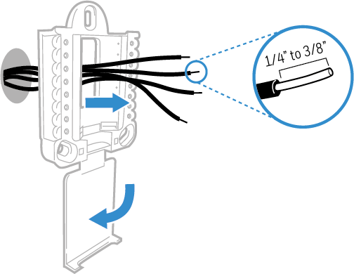
Bundle and insert wires through the UWP Wall Plate. Pull open the wall plate and insert the bundle of wires through the back. Make sure at least 1/4 inch of each wire’s metal conductor is exposed for easy insertion into the wire terminal.
-
Position the wall plate. Center and level the wall plate over the hole in the wall.
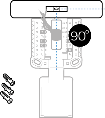
-
Mark the holes for the fasteners. Use wall plate as a template.
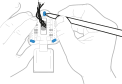
-
Drill holes for the anchors. Use a 3/16th inch drill bit.
-
Insert the wall anchors. Use a hammer to carefully tap the anchors into the holes until flush with the wall.
Wiring
Improper wiring or configuring of your thermostat can cause unintended operation of your HVAC system which could lead to property damage, injury, including death. If you are unsure of what type of system you have, refer to your heating/cooling system equipment literature or call an HVAC professional.
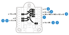
The UWP Wall Plate you mounted has more terminals than you will need. Insert the matched wires you’ve already labeled into the terminal with same letter on the Wall Plate.
If the labels do not match exactly, review the alternate wiring sections below to find the diagram for your system type.
If you have difficulty inserting wires, you may have to press down the terminal push button next to the corresponding terminal.
-
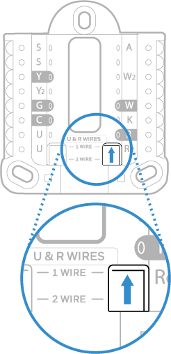
Set R-switch position and insert R-wire or wires. Set the R-switch up or down based on your wiring notes in Step 7 of the section Removing the Old Thermostat.
Insert wires into the inner holes of the terminals on the UWP. The tabs will stay down once the wire is inserted.
Alternate wiring options are shown on the following pages.
|
If you have 1 R-wire (R,Rh, or Rc) |
|
|
|
|
or |
|
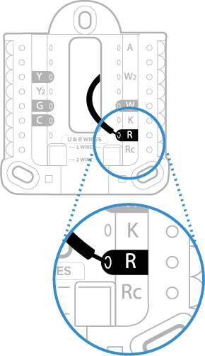
|
If you have 2 R-wires (R or Rh, and Rc) |
|
|
|
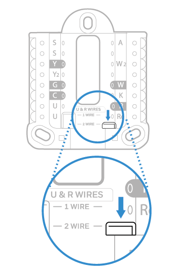
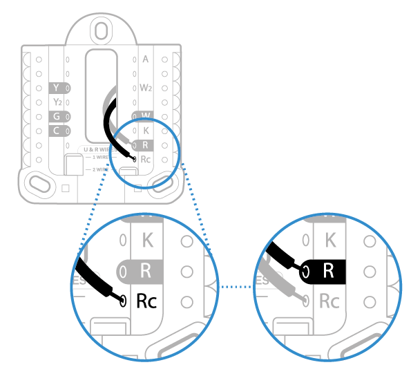
-
Connect wires to the UWP. Refer to the notes you recorded on the chart during removal.
Press down on the tabs to put the wires into the inner holes of their corresponding terminals on the UWP (one wire per terminal) until it is firmly in place.
Gently tug on the wires to verify that they are secure.
If you need to release the wires again, push down the terminal tabs on the sides of the UWP.
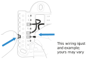
-
Confirm wiring matches snapshot. Confirm wiring matches terminals from the photo you took during removal.
-
Mount the UWP and close the door. Mount the UWP using the provided screws. Install all three screws for a secure fit on your wall. Close the door after you’re finished.

-
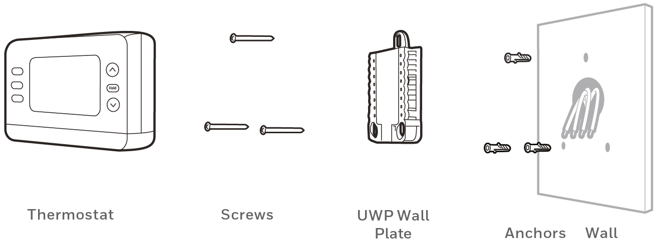
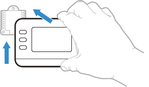
Install batteries. Insert two AA alkaline batteries in the back of the thermostat as shown.
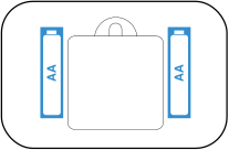
-
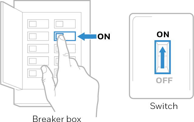
Turn the power ON. Turn on the power at the breaker box or switch that controls the heating/cooling system.
Alternate Wiring for Conventional Systems
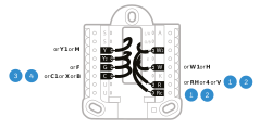
If labels do not match terminals, connect wires as shown below (see notes below).
WIRING NOTES:
-
If you must connect both R and Rc wires, set the R Slider Tab to the down position (2 wires).
-
If your old thermostat had both R and RH wires, set the R Slider Tab to the down position (2 wires). Then connect the R wire to the Rc terminal, and the RH wire to the R terminal.
-
If your old thermostat had only 1 C or C1 wire, connect it to the C terminal. If your old thermostat had 2 C or C1 wires, wrap each separately with electrical tape and do not connect them.
-
C does not power the thermostat display or operations; batteries are always required.
Alternate Wiring for Heat Pumps
-
Keep the R Slider Tab in the up position (1 wire).
-
If your old thermostat had both V and VR wires, stop now and contact a qualified contractor for help.
-
If your old thermostat had separate O and B wires, attach the B wire to the C terminal. If another wire is attached to the C terminal, stop now and contact a qualified contractor for help.
-
If your old thermostat had Y1, W1 and W2 wires, stop now and contact a qualified contractor for help.
-
C does not power the thermostat display or its operations; batteries are always required.
-
This model doesn’t support the heat pump fault alert (L/A terminal). If this is desired, please contact a contractor for replacement model.
-
Either Aux or E from old thermostat wires to Aux on new thermostat.
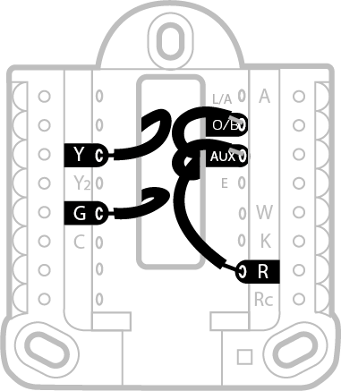
Do NOT use W for heat pump applications. Auxiliary heat must wire to AUX.
Accent Piece Replacement
One white and one grey accent piece are provided with the RTH21B/RTHC21B and RTH22B/RTHC22B thermostats to accommodate different user preferences.
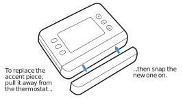
See the video below.